|
|
|
Usuarios conectados
Actualmente hay 6043 visitantes online. |
|
Productos
|
|
Información
|
|
Destacado
|
|
|
 |
|
|
No hay comentarios de productos.
X-HMD01, X-HMD03, X-HX99, X-HX05
6. ADJUSTMENT
6.1 CD SECTION
Note : There is no information to be shown in this section.
6.2 MD SECTION
Note : There is no information to be shown in this section.
6.3 TUNER SECTION
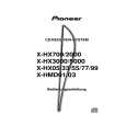
6.3.1 FM Tuner Section
� Set the mode selector to FM BAND. � Connect the wiring as shown in Fig. 1.
Step No. Adjustment Title FM SG (1kHz, ± 75kHz dev.) Frequency (MHz) Level (dBµV) Reception Frequency Display Adjustment Location Specifications � Adjust L7 so that the voltaghe between TP8 (+) and TP9 (�) becomes 0V ± 50mV. � Check the waveform with the oscilloscope, and confirm so that the output level is about �11 ± 2dBV and THD is about 0.5 ± 0.1%. Confirm that the "TUNE" indicator in the LCD is turned on.
1
DET. waveform Coil Adjustment
98
60
98MHz
L7
6.3.2 AM Tuner Section
� Set the mode selector to AM BAND. � Connect the wiring as shown in Fig. 1.
Step No. Vt 1 (Tuning Voltage Adjustment) Adjustment Title AM SG (400Hz, 30% Mod.) Frequency Level (kHz) (dBµV/m) 530 1700 � � Reception Frequency Display 530kHz 1700kHz Adjustment Location L2 � Specifications � Adjust L2 so that the voltage between TP6 (+) and TP7 (�) becomes 1.0V. � Set the reception frequency to 1700 kHz and confirm that the voltage is about 6.6V. 1. Connect an electrolytic capacitor of about 10µF to TP9 (TP9 side is +), and terminate with TP10 by a resistor of about 47k�. Connect the sweep input to the both ends of terminated resistor. 2. Adjust T1 so that the marker of 450kHz ± 3kHz becomes the same level (single-peak characteristic of IF becomes symmetrical). 3. Input 74dBµV from the SSG, confirm the waveform of output signal so that the output level is �27V ± 2dBV and THD is about 1 ± 0.5%. And confirm that the "TUNE" indicator in the LCD is turned on. Connect an oscilloscope to TP3 (L) and TP4 (R), and adjust L1 (600kHz) and TC1 (1400kHz) repeatedly so that the output level becomes maximum.
2
IFT Adjustment
1000
S/N about 10dB
1000kHz
T1
3
Tracking Adjustment
600 1400
50 (S/N about 10dB)
600kHz 1400kHz
L1 TC1
56
|
|
|
> |
|